 ar
ar bg
bg hr
hr cs
cs da
da nl
nl fi
fi fr
fr de
de el
el hi
hi it
it ko
ko no
no pl
pl pt
pt ro
ro ru
ru es
es sv
sv tl
tl iw
iw id
id lv
lv lt
lt sr
sr sk
sk sl
sl uk
uk vi
vi et
et hu
hu th
th tr
tr fa
fa ms
ms hy
hy ka
ka ur
ur bn
bn mn
mn ta
ta kk
kk uz
uz ku
ku
load cell wiring diagram
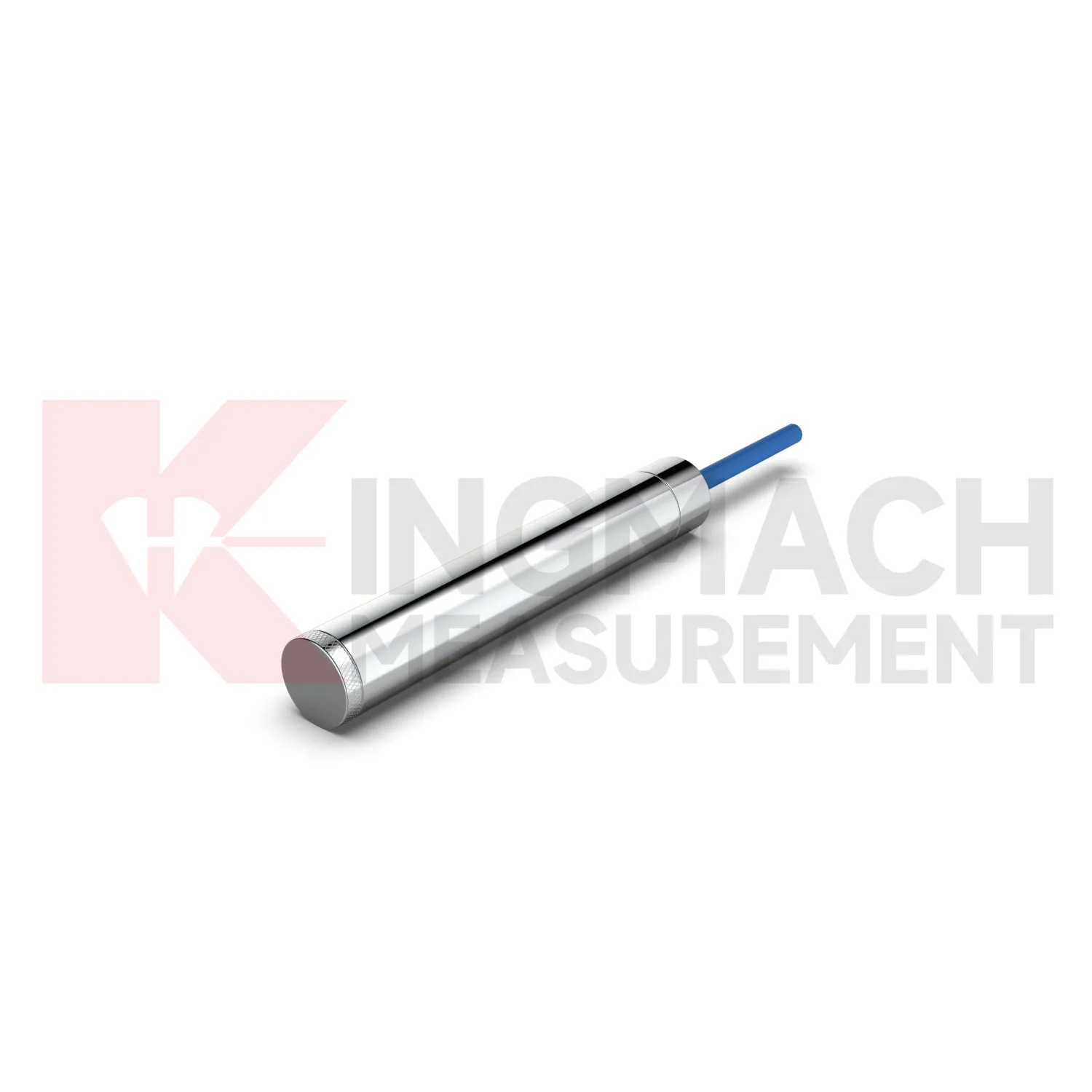
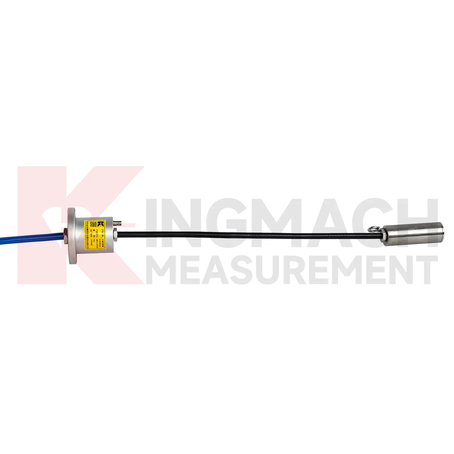
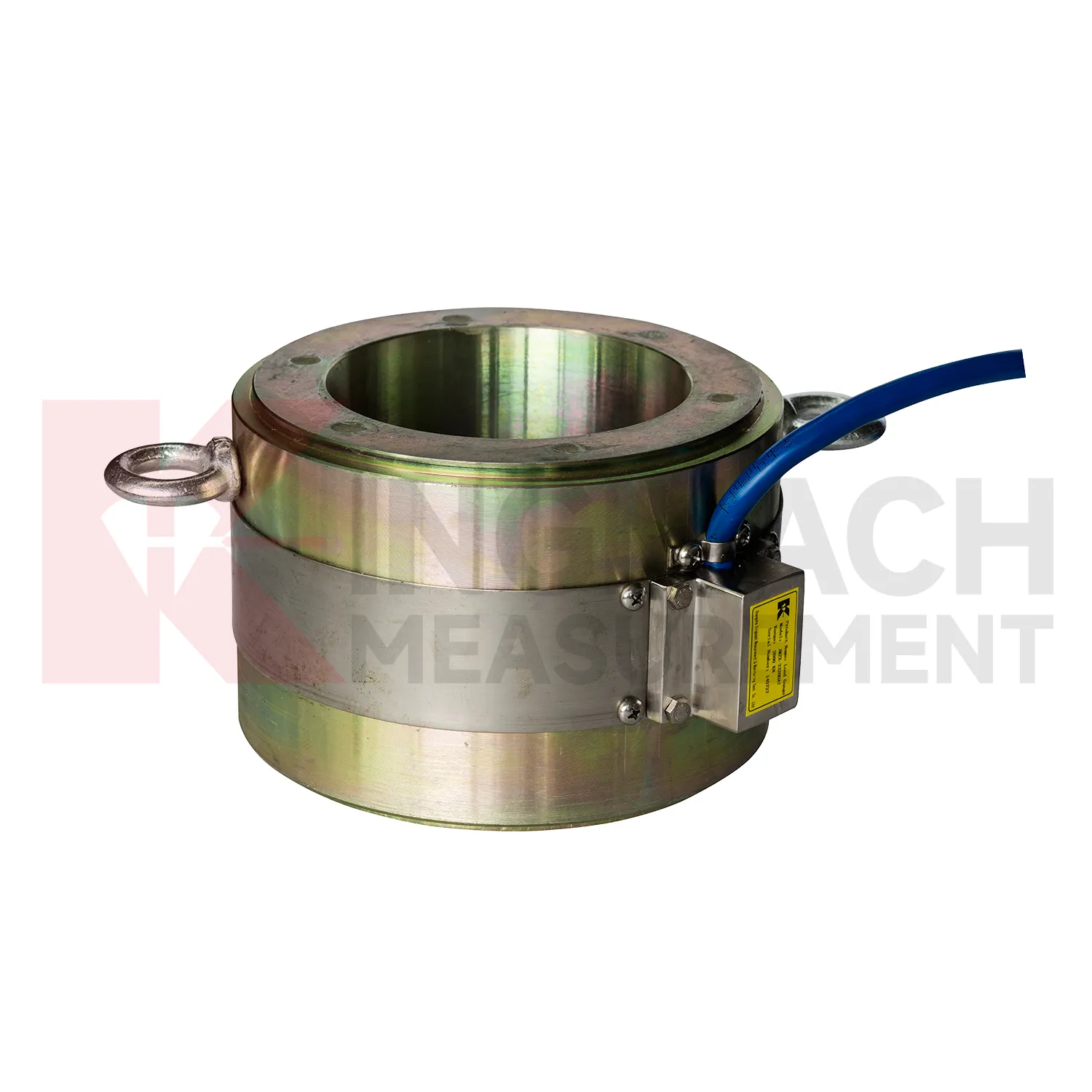
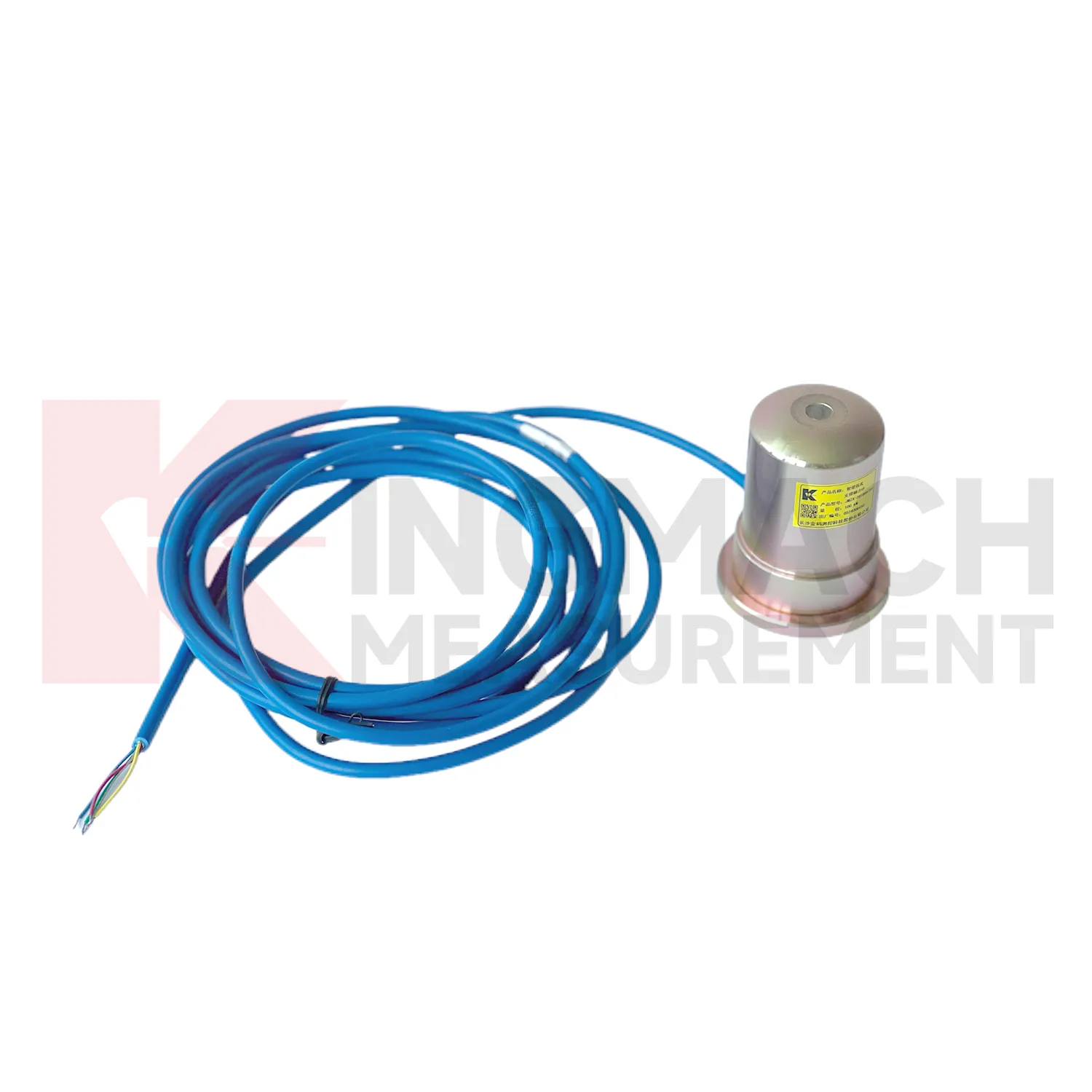
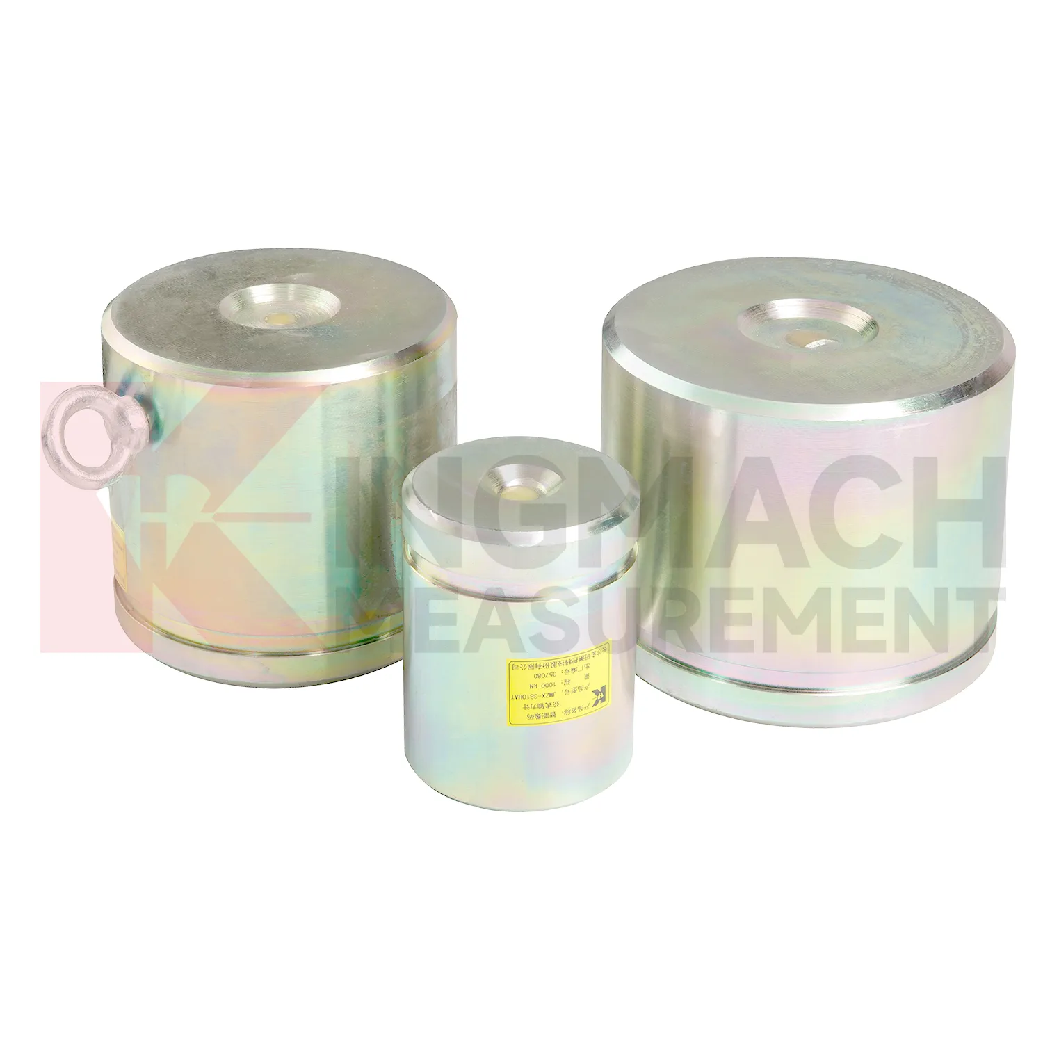
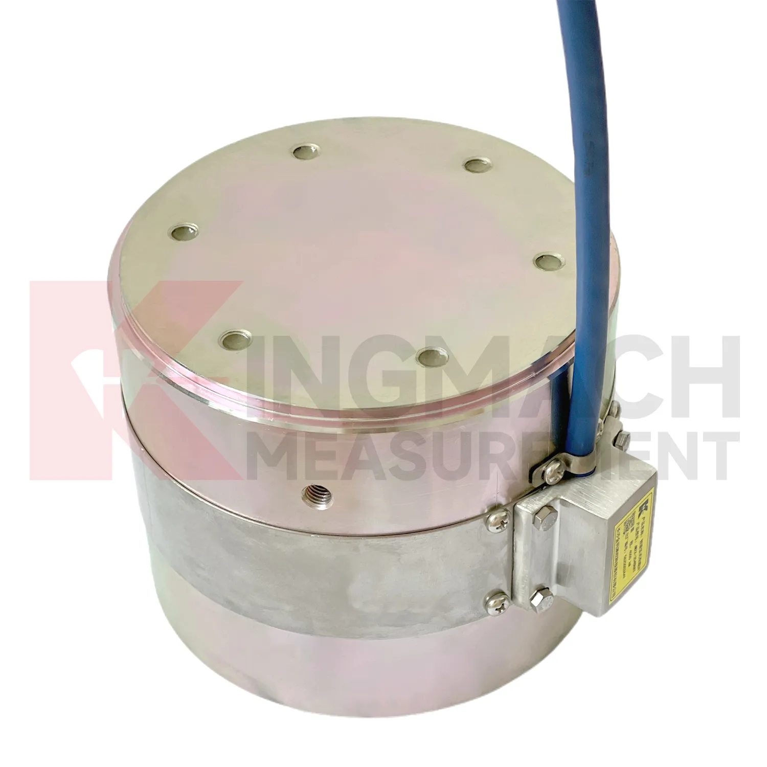
Kingmach load cell wiring diagram can be specified as part of a complete monitoring workflow rather than as a standalone instrument. Product pages mention manual readout compatibility, comprehensive vibrating wire readouts, automated acquisition, and storage of model or calibration information inside smart sensors. On listed models, force ranges extend from 200 kN on smaller axial force meters to 10000 kN on high capacity solid load cells, while pressure related models cover 0.3 MPa to 8 MPa. The presence of temperature correction, waterproof construction, digital output, and stable vibrating wire sensing helps the same installation work through construction and service periods. Kingmach's support range includes data loggers, instrumentation cables, and visualization software, so project teams can plan channel naming, alarm limits, report format, and maintenance inspection around the sensor from the beginning. That reduces later confusion when hundreds of monitoring points are installed across a bridge, subway, dam, slope, or foundation project. Viewed as a package, the product, readout, cable, calibration record, and software connection all affect data quality. Kingmach's catalog structure helps buyers think about that whole chain rather than treating the sensor as a loose component. For long projects, that shared record reduces confusion when installation teams, monitoring teams, and maintenance teams are not the same people.
Application of load cell wiring diagram
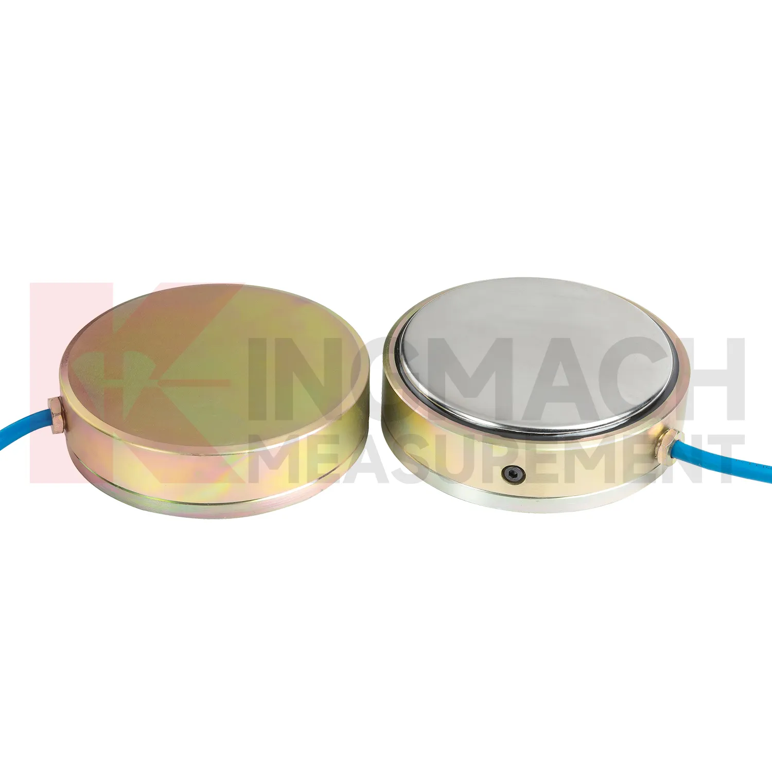
In foundation pit projects, load cell wiring diagram supports strut force monitoring, anchor load control, retaining wall pressure checks, and load transfer review as soil is removed. The painful part of this work is timing: force can rise quickly after excavation, rainfall, dewatering, or support adjustment, while the working area is still changing every day. The axial force meter JMZX-38XXHAT covers 200 kN to 3000 kN and provides 0.5%FS accuracy with direct kN display. For soil pressure at retaining structures, the JMZX-50XXAT/ATM earth pressure cell line covers 0.3 MPa to 8 MPa with 0.001 MPa resolution and 0.5%FS pressure accuracy. These numbers give the monitoring team enough detail to track staged construction rather than only final condition. Good use also depends on bearing plates, adequate surface strength, cable protection, waterproof connectors, and a reading plan after each excavation layer. The force record should be compared with settlement, horizontal displacement, water pressure, and nearby construction notes. If automated monitoring is used, alarm thresholds should be tied to excavation stages rather than copied across all channels. A strut close to the active excavation face may behave differently from one several levels above, even when the same instrument model is used.
The future of load cell wiring diagram
The next stage for load cell wiring diagram in infrastructure monitoring is tighter integration with site data systems. Smart sensors already store model data, calibration coefficients, zero values, temperature readings, and measurement records on selected Kingmach products. The practical path is to connect that identity data with 4G, LoRa, wired acquisition, or 5G gateways, then place the force trend beside displacement, settlement, pore pressure, and rainfall in the same review screen. This matters because future warnings will be less about one limit value and more about patterns: force rising after excavation, anchor load falling after heavy rain, or bridge cable force drifting during seasonal temperature cycles. Digital twin models can use those readings when the sensor location, range, and calibration background are reliable. Standards and owner specifications for structural health monitoring are also becoming more data traceability focused, which favors instruments that can carry their own calibration identity and remain readable through long service periods.
Care & Maintenance of load cell wiring diagram
For load cell wiring diagram used with manual readouts, care depends on repeatable procedure. Before installation, store the calibration sheet with the instrument and confirm that the readout supports the sensor type. Kingmach product pages mention compatible readouts and comprehensive vibrating wire instruments, which can display force values directly on selected models. During installation, label the cable and channel clearly, record the zero value, and protect the connection point from water and pulling. During each reading round, use the same unit, readout setting, point name, and observation sequence. Note temperature, weather, construction activity, and any visible damage near the sensor. Long term maintenance should include connector cleaning, cable jacket inspection, comparison with nearby points, and periodic calibration planning according to project requirements. If a reading seems wrong, repeat it after checking the cable and readout battery. Many apparent sensor faults come from swapped channels, loose connectors, or missing zero records. Use the same readout settings.
Kingmach load cell wiring diagram
load cell wiring diagram often sits between design intent and field behavior. Drawings may state the expected force, but site loading can change when excavation sequence, concrete curing, traffic, reservoir level, grouting, or prestressing work changes. Kingmach supplies sensors and acquisition equipment for bridges, tunnels, dams, subways, slopes, foundations, railways, buildings, and hydropower projects. In these settings, the sensor helps reveal whether a member is carrying its share of the load or taking more than expected. The instrument must fit the force range, the bearing surface, the environmental exposure, and the data workflow. A high capacity sensor with poor installation records is still hard to trust. A moderate range sensor with clear calibration, stable zero, protected cable, and a clean reading plan can produce stronger evidence. For that reason, force monitoring should be planned alongside installation details, not added after the site has already become crowded. This is especially useful when the monitored point becomes hidden after the next work stage.
FAQ
Q: Can load cell wiring diagram be used for soil pressure or retaining wall pressure? A: Yes, pressure related models such as earth pressure cells are used where the measured value is contact pressure rather than direct member force. Q: What ranges are listed for Kingmach earth pressure cells? A: The JMZX-50XXAT/ATM family lists 0.3 MPa, 0.6 MPa, 1 MPa, 2 MPa, 4 MPa, 6 MPa, and 8 MPa ranges. Q: What accuracy and resolution are listed? A: The product file gives 0.001 MPa pressure resolution, 0.5%FS pressure accuracy, and ±0.5°C temperature accuracy. Q: Where are these readings useful? A: Foundation pits, dams, slopes, retaining walls, embankments, tunnels, and buried structures. Q: What maintenance issue is most common? A: Cable damage, water entry, channel confusion, and poor installation records cause many field doubts.
Reviews
Ryan Lewis
Fast delivery and excellent product quality. The accelerometers and tiltmeters are highly reliable. Strongly recommend this company.
James Thompson
The tiltmeters and accelerometers are very sensitive and provide precise data. Perfect for our structural health monitoring system.
Latest Inquiries
To protect the privacy of our buyers, only public service email domains like Gmail, Yahoo, and MSN will be displayed. Additionally, only a limited portion of the inquiry content will be shown.
Harper***@gmail.comIndia
Dear Sir, we are planning to procure a complete monitoring system including strain gauges, tiltmeter...
Ava***@gmail.comAustralia
Hi, I am looking for reliable tiltmeters and accelerometers for structural health monitoring. Please...