
 EN
EN
 ar
ar bg
bg hr
hr cs
cs da
da nl
nl fi
fi fr
fr de
de el
el hi
hi it
it ko
ko no
no pl
pl pt
pt ro
ro ru
ru es
es sv
sv tl
tl iw
iw id
id lv
lv lt
lt sr
sr sk
sk sl
sl uk
uk vi
vi et
et hu
hu th
th tr
tr fa
fa ms
ms hy
hy ka
ka ur
ur bn
bn mn
mn ta
ta kk
kk uz
uz ku
ku
Real-Time Dam Safety Alerts with Differential Pressure Water Level Sensors
Key Takeaways An alert chain needs more than a sensor: define field in...

Wheatstone Bridge in Strain Gauge: What Actually Matters
A few microvolts of drift can turn a week’s worth of strain data into noise. When you’re tracking stress on a concrete pile or steel girder, the way the Wheatstone bridge in your strain gauge is wired often decides whether the numbers hold up. It’s not just the textbook circuit—quarter, half, full bridge—it’s the cable runs, the temperature swings, and how those three resistors and one strain gauge actually behave after sitting in the sun for six months. We see a lot of field crews chasing midday jumps in the readings, and nine times out of ten it’s a ground loop or unbalanced lead wires. Understanding those failure modes is more useful than any idealized diagram. This page breaks down the link between bridge configuration and real-world accuracy, without the fluff.
Technical Detail
In strain gauge measurements, the Wheatstone bridge converts tiny resistance changes into a voltage you can work with, typically in the 0–10 mV range for a full bridge at 2 mV/V excitation. But that signal rarely stays clean without attention to the whole circuit. Kingmach supplies geotechnical sensors that rely on these bridge configurations, and the support calls we get point to the same weak spots: lead wire effects, temperature drift, and miswired junctions. A quarter‑bridge setup, using a single active gauge and three fixed resistors, is common for simplicity but leaves you wide open to thermal errors and cable resistance unless you run a three‑wire connection. The extra wire balances out the lead resistance in the two active arms—a trick that still gets overlooked. Half‑bridge and full‑bridge arrangements cancel temperature effects mechanically when gauges are placed on adjacent arms, which is why most long‑term embedding strain gauges use a full Wheatstone bridge right at the sensing location. That self‑compensation becomes critical once ambient temperature swings past 15–20°C during a monitoring cycle. Gauge resistance also matters more than datasheets suggest. 120 Ω gauges draw higher current, which warms the bonding surface on materials with poor thermal conductivity; 350 Ω gauges run cooler and are often the safer pick for composites or plastics. Matching the bridge completion resistor tolerance to the intended strain range is another detail—using 0.1% resistors instead of 1% can halve the initial offset error for low‑strain scenarios. Kingmach instruments are built with these wiring and compensation headaches in mind. We standardize on full‑bridge configurations for our embedment and spot‑weldable strain gauges, offer pre‑terminated multi‑core shielded cables, and can custom‑select gauge resistance and temperature compensation to match your substrate. Our documentation includes clear wiring diagrams and troubleshooting guides, so the installation crew can trace issues without calling an engineer. For projects that need a specific excitation voltage or output scaling, we configure the board‑level bridge balance and gain settings during production. Drop us a note if the catalog specs don’t line up with your logger’s input range—we routinely adjust these for noise‑sensitive sites.
News
Key Takeaways An alert chain needs more than a sensor: define field in...

Key Takeaways The strongest fit is usually a confined, submerged, or s...
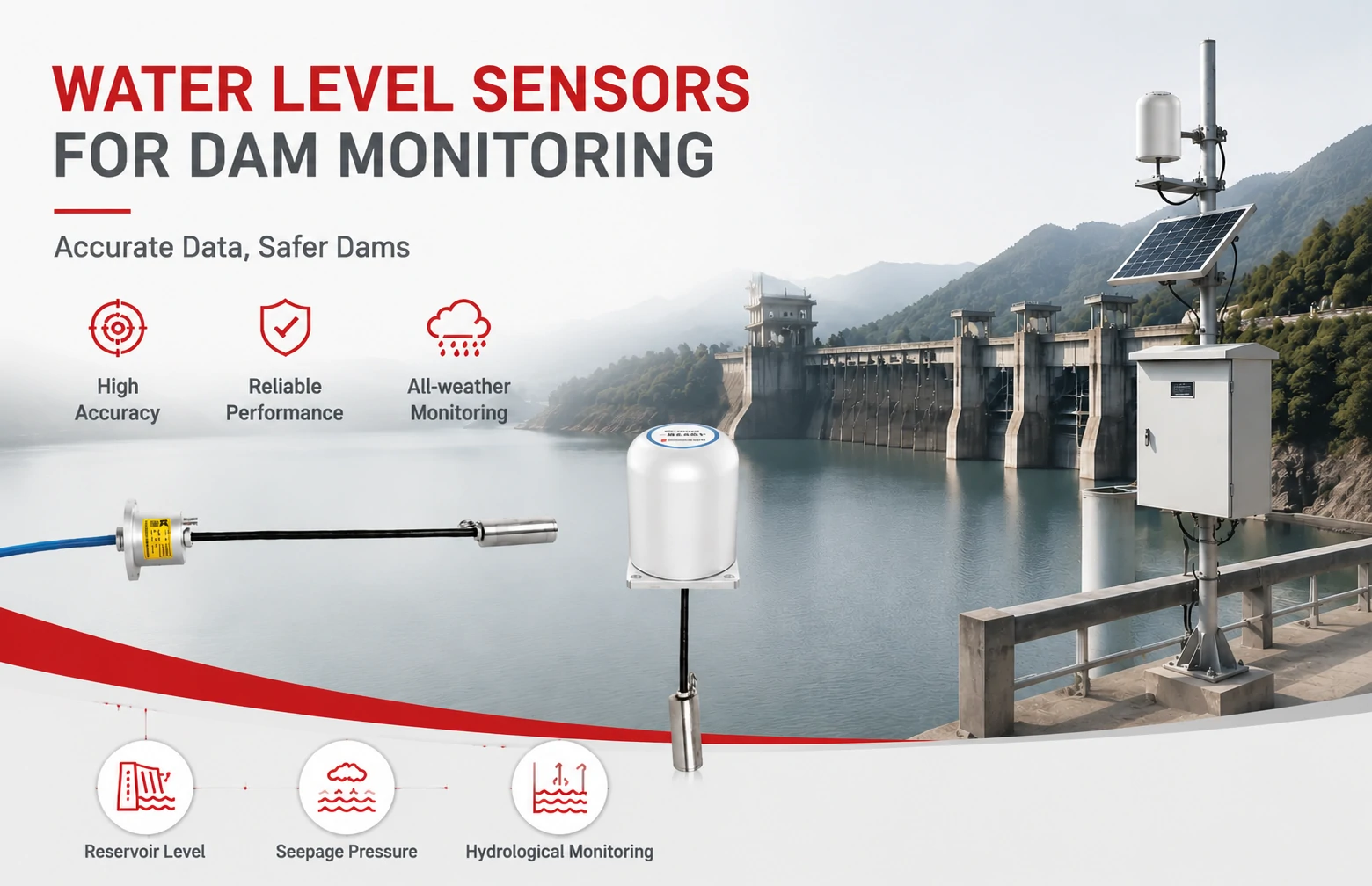
Kingmach Water Level Sensors for Dam Monitoring: A Buyer's Guide to Differential Pre...
Products
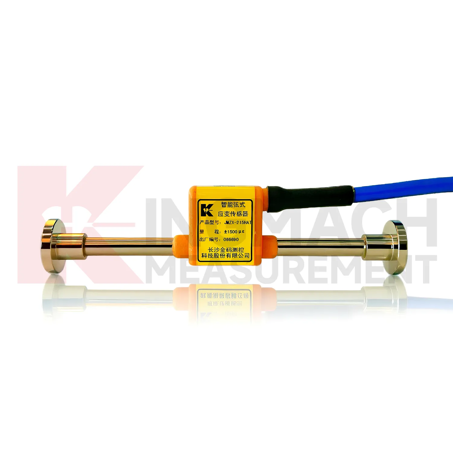
Smart vibrating wire strain gauge (embedment model) JMZX-215HA/215HAT/HB
View Details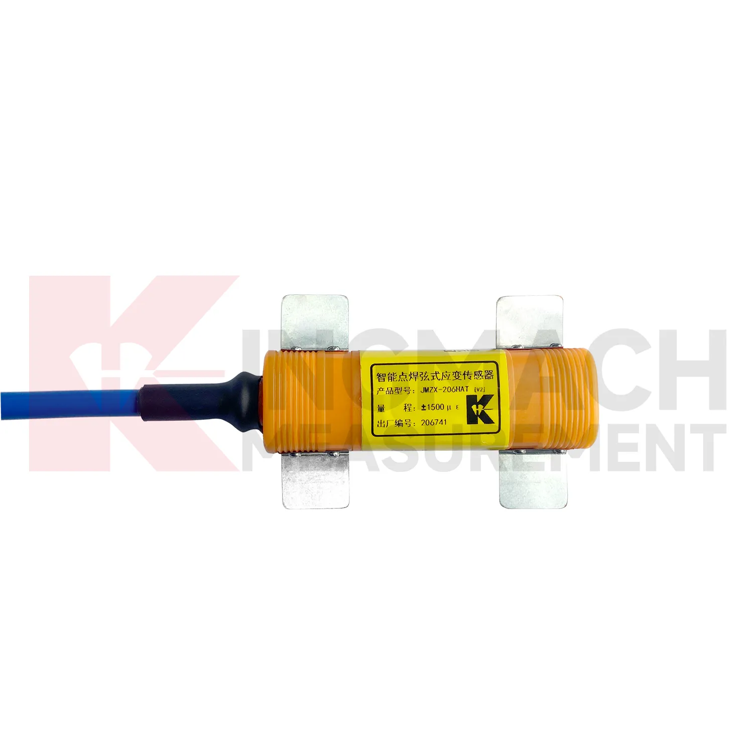
Smart vibrating wire strain gauge (surface welded model) JMZX-206HAT
View Details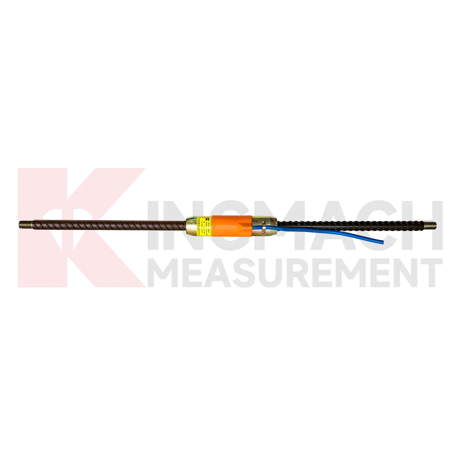
Rebar Strainmeters ( VW & Smart Type) JMZX-4XXHAT/HB
View DetailsFAQ
In a two‑wire hookup, the lead resistance appears in series with the gauge arm, shifting the zero and reducing the effective gauge factor as temperature changes the wire resistance. With three wires, you bring two wires to one gauge end and one to the other. The bridge sees two equal lengths in adjacent arms, so the lead resistance cancels out—assuming the wire gauge and length are matched. It’s a quick upgrade that costs you one extra conductor, and it works best when all three wires are run together in the same cable bundle.
The choice mainly affects self‑heating and cable compatibility. A 120Ω gauge passes more current for a given excitation voltage, so it can locally heat the surface by a few degrees on low‑conductivity materials like plastic or wood—enough to skew readings if you don’t account for it. 350Ω gauges draw less current and tend to stay cooler. The other trade‑off: 120Ω circuits are slightly less sensitive to leakage resistance in wet environments, but 350Ω gauges are less affected by long cable resistance in large structures. Most of our long‑term monitoring installations default to 350Ω unless the client’s logger is optimized for 120Ω inputs.
The hardware method is to use a dummy gauge mounted on an unstrained piece of the same material, placed in an adjacent bridge arm. When temperature changes, both the active and dummy gauges shift similarly, so the bridge output cancels the thermal apparent strain. For full‑bridge sensors, you can arrange the four gauges so that two sense tensile strain and two sense compressive strain from the same temperature field—that gives both temperature compensation and roughly double the signal. Kingmach’s embedment gauges are built this way, so the output you get already has temperature effects largely canceled. If you’re using a quarter‑bridge with no dummy, you’ll need a reliable temperature curve for the gauge on that substrate, and even then, field results drift during rapid temperature shifts.
First, check the bridge completion wiring. A common mistake is misidentifying the sense and excitation leads on full‑bridge sensors, especially when using modular connector systems. Measure the resistance at the connector pins with a multimeter: between excitation lines you should see around the nominal bridge resistance (e.g., 120Ω or 350Ω), and between sense lines roughly the same. If one arm reads open, check for a broken gauge or solder joint. Also verify insulation resistance to ground—moisture ingress can create a parallel path that corrupts the millivolt output. If the readings jump with weather changes, look for galvanic corrosion at the terminals or insufficient cable shielding. We provide a step‑by‑step resistance check diagram with our sensors; it catches most field wiring errors before they become data headaches.
Some loggers only read full‑bridge sensors, expecting the completion to be done externally. For quarter‑bridge or half‑bridge setups, you need an external completion module with precision resistors. The module should match the gauge resistance and have low‑drift resistors. If you’re retrofitting an older logger, look for a completion box with a balance potentiometer and a shunt calibration switch so you can verify the output during installation. Kingmach can supply completion modules tailored to common gauge resistances and excitation voltages, or build the whole bridge into the sensor itself for a plug‑and‑play full‑bridge output.
Share your product type, target capacity, and application requirements. Our team can review the details and recommend a practical next step.
If you are interested in our products or want to become our partner.
Please leave your contact information, our team will contact you as soon as possible.
Mail: [email protected]
Contact Us: +8613808434127
Address: No. 188 Tongzipo West Rd, Changsha, Hunan, China